Innovation is characterized as the creation of better or more effective ideas, products, processes or technologies. Over the past twenty-five years, there have been major innovations within our specialized niche of designing and constructing distribution facilities. The innovations highlighted in the following sections are just a sampling of the new and creative ideas available to our industry.
Case Study: Port of Portland T6 Porous Pavement
Porous Pavement
Porous Pavement Overview
Porous pavement provides an alternative to traditional storm water management systems. Porous paving is constructed to allow water infiltration, while maintaining most of the structural characteristics of asphalt pavement. A porous system eliminates the need for extensive piping, catch basins, and other infrastructure typically required for traditional storm water drainage. Porous systems accomplish several important environmental goals, including reductions of run-off temperature, velocity, volume, and pollutants. Surface accumulations of storm water during critical events are almost entirely mitigated. In considering whether or not a porous paving system should be pursued, the condition of the sub grade and underlying soils must be evaluated for drainage purposes. For example, a primarily sand sub grade will allow for high infiltration, whereas a denser clay sub grade may prove to be unsuitable for porous systems.
Porous pavements offer a green approach to storm water treatment that reduces the need for storm water control structures. By mimicking natural processes, the resulting infiltration is of a much higher quality than that of conventionally managed run-off. Moreover, porous pavement reduces contaminants such as total suspended solids, metals, and oil and also improves the treatment of nitrates, phosphates, and other anthropogenic compounds. Porous pavement systems can also assist in recharging local aquifers through the natural infiltration process.
Central to any feasibility analysis is cost. On its face, porous pavement is slightly more expensive than traditional asphalt. Recent studies indicate that porous asphalt costs between ten to twenty percent more than standard asphalt, on a unit basis. In addition to the increased pavement cost, the underlying stone bed, which is generally deeper than a conventional aggregate sub-base and wrapped in geotextile fabric, is also more expensive. Two major contributors to the higher initial costs of porous pavement are a limited number of experienced vendors to install the pavement, and the requirement that the asphalt batch be produced separately. The engineer/contractor must know the specifications to send to the producer who then manufactures a special load of porous asphalt. However, when other factors such as storm water fees and physical infrastructure are included in the analysis, the cost gap between conventional asphalt and porous pavement diminishes. Also, there generally is less earthwork involved because porous systems can be incorporated into the site’s natural topography. When all factors are considered, porous paving systems with infiltration have proven to be competitive with, and often less expensive than conventional impervious surfaces with traditional storm water management infrastructure.
Traditional asphalt requires resealing every few years. In contrast, porous pavement requires no resealing but does demand vacuuming to remove material that can clog the void space. Porous pavement, due to its reduced fines, is susceptible to crushing by heavy loadings. The very underlying soils that make porous pavement an attractive option also have a downside: high permeability sub grades have the potential to develop anaerobic conditions. Finally, in the event of a spill, both surface types will require removal, excavation and site remediation, though porous pavement can make the cleanup more difficult due to absorption in the pores. If installed properly and maintained to the specifications of the engineer, porous pavement has a long lifespan; existing systems dating back several decades are still functional today.
Maintenance & Repairs
The maintenance required for porous pavement systems is not necessarily intensive but it remains important nonetheless. The major intent of system upkeep is to prevent the pavement surface and infiltration bed from becoming clogged with fines (sediments). Superficial dirt will not necessarily clog the pavement voids, but if the dirt is ground-in repeatedly by tires, this can have adverse affects on the system. Thus, trucks and other heavy equipment should be prevented from tracking or spilling dirt onto the porous pavement and their travel across the surface should be limited.
Keeping the paving clean throughout the year will prolong its life span. Using a commercial cleaning unit to vacuum the surface two to three times per year is highly recommended. Pavement washing systems, compressed air units, and pressure washers should not be used because they will degrade the structural integrity of the surface. Any inlet structures in the infiltration beds should also be cleaned annually or biannually, if possible. Porous pavement surfaces should never be seal coated.
If there are swales or landscaped areas adjacent to porous pavement, these should be well maintained in order to prevent an overflow or washout, which can deposit sediments on the porous surface. If any bare spots or eroded areas are observed, steps should be taken to stabilize the region so that overflow dangers are mitigated.
While potholes in the porous pavement are unlikely, soft spots in the sub grade can cause minor areas to sink several inches. These small potholes are called declivities. TransDevelopment has observed that the soft spots did not suffer from any surface buckling due to the flexibility of the wearing surface. For damaged areas of less than fifty square feet, a declivity can be patched with standard impervious paving. Since the area is small, any increased runoff from the conventional surface patch will infiltrate in the adjacent porous area. If there is a major event that causes a declivity of more than fifty square feet, both porous and traditional asphalt can be considered. At this time, the site should undergo an inspection by the engineer to determine why a relatively large area suffered from a soft spot issue.
Winter Conditions
Porous pavements perform well in colder, northern climates. Because water drains through the surface and into the subsurface bed, freeze-thaw cycles usually do not adversely affect the paving. The systems actually are less prone to forming black ice. Winter maintenance for a porous pavement area may be necessary but is less intensive than what is required for a traditional impervious surface. A porous pavement system with a subsurface aggregate bed has superior snow melting characteristics because the stone bed will absorb and retain heat. Therefore, freezing rain and snow melt faster on porous pavement accumulation of ice and light snow is generally not problematic.
It is important to consider heavier storm events where larger volumes of snow will be deposited on the porous surface. During and after these storms, snow plowing is acceptable as long as the operator is careful and sets the blade slightly higher than usual. Abrasive materials for traction and melting such as sand or cinders should not be applied on or near the porous paving. Salt can be used to de-ice the porous pavement; however, alternative deicers are recommended for environmental reasons. Lastly, during these storms, porous pavement provides better traction for humans and automobile tires in rain and snow.
Controlling Critical Storm Events
Most porous pavement systems that rely on infiltration are designed to handle critical storm events that occur between once every two years and once every ten years. Designers should also study a rare once-in-a-century storm event’s potential effects on the porous paving system. In order to handle the extreme volumes of water and a possible overwhelming of infiltration capacity, the stone bed can be designed with an overflow control structure. During large storm events, peak rates are controlled, so at no time can the water rise to the pavement level.
Perforated pipes or French drains along the bottom aggregate bed may be used to evenly distribute runoff over the entire bed bottom. Continuously perforated pipes can also be used to connect any underground infrastructure to provide outflow. Depending on size, the pipes themselves may provide additional water storage. Bypass systems can be designed but these structures should always maintain positive outflow.
Design & Construction Notes
In areas with poorly draining soils, infiltration beds below the surface can be designed to assist with slow discharge. In areas such as truck loading zones, where the threat of spills and groundwater contamination is heightened, porous pavement is not as suitable as conventional impervious paving. Due to the frequency of spills and the heavier-duty load requirements of haul away loading areas, these surfaces are better of being paved traditionally. Runoff from the truck and heavy equipment area can be treated with oil water separators and other filters before infiltrating into an adjacent bioswale.
Due to the activities inherent to construction, porous pavement should be installed as close to the end of other construction as possible. It is during this construction phase that porous pavement is most vulnerable to failure; special care must be taken to reduce the compaction of underlying soils, the contamination of infiltration base with sediment and fines, and the tracking of sediment by equipment. Also, any onsite drainage containing sediments should be diverted from the porous surface or constructed bed.
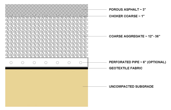
Immediately after the sub grade is prepared by raking and ripping, the geotextile fabric should be placed. The mat should be placed to the specifications and recommendations of the manufacturer and secured several feet outside of the stone bed to prevent runoff and sediment from infiltrating. After the site has stabilized and the installation is completed, excess geotextile can be cut back to the edge of the wearing surface. Base aggregate should be laid next after the geotextile fabric is spread, immediately followed by the choker coarse and the wearing surface (asphalt, open graded Portland cement, etc.). Porous pavement should not be installed on wet surfaces or when the air temperature is below fifty degrees Fahrenheit.
Following the completion of the porous paving installation, the permeability of the pavement surface should be tested. This can be accomplished by applying water at a rate of at least 5 gallons per minute on the surface with the use of a hose. Engineers should verify that the water infiltrates the surface directly without forming a puddle or runoff. In addition, it is recommended that the owner retain a third party to test the integrity and functionality of the system under the required state and federal safety regulations.
Specifications Overview
The specifications outlined below represent the guidelines used by several states including Florida and Pennsylvania for porous pavement installations. Many of the specifications have been refined by Cahill Associates and were implemented in the Port of Portland’s Terminal 6 expansion. These are not all-encompassing specifications and should not be treated as such. The engineer and contractor must adapt materials and specifications to the specific needs of each project. Additionally, the specific standards for each material were intentionally omitted from this document.
- Base aggregate
- The infiltration bed should be between 12-36 inches deep and comprised of clean, uniformly graded aggregate.
- The depth of the bed is a function of storm water storage requirements, frost depth considerations, site grading, and predicted loading.
- Stone for infiltration beds should be uniformly graded coarse aggregate (AASHTO No. 3) with one to two inches of gradation.
- Aggregate should not have wash loss of more than 0.5% and should have about 40% void space, depending on the application.
- Choker base coarse aggregate should be installed uniformly over the base aggregate in order to provide an even surface for paving.
- Height should 3/8 inch to 3/4 inch of uniformly graded AASHTO No. 57.
- Geotextile fabric
- Geotextile cover should consist of needled, non woven polypropylene fibers
- Examples of acceptable products: Mirafi 140N, Amoco 4547, and Geotex 451
- Piping
- Pipe shall be continuously perforated with a smooth interior.
- The minimum inside diameter should be about six inches.
- High-density polyethylene pipe should meet AASHTO standards.
- Stormwater Structures
- Standard inlet boxes should be modified to provide a minimum of 12" sump storage.
- These inlets should have bottom-leaching basins and open to gravel sumps when situated in the infiltration bed.
- Any PVC catch basins, clean outs, and drains should have H-rated grating.
- Steel reinforcing bars installed over the outlet structure should conform to ASTM standards.
- Pre-cast concrete inlets may be substituted for cast-in-place structures.
- Wearing Surface
- For porous paving, bituminous surface course or Portland cement pervious pavement mixtures can be used.
- Consult with engineer, contractor, and manufacturer for material selection, production, and installation.
- This document makes no attempt to capture all of the necessary specifications for the wearing surface.
Spill Containment
Spill Containment
Cargo transfers between rail and truck are an essential part of industrial distribution, and require careful planning for spill containment in the unlikely event of product release. In addition to programs such as Hazardous Materials Management (HMM) and Emergency Action Plans (EAP), intermodal facility best practices require formalized transfer and containment system processes. A transfer system combines the use of specially designed equipment for trans-loading operations with redundant safety systems, specialized training and operational practices to prevent a product release. The terminal containment system combines site design features, specialized infrastructure and equipment, and practices to contain a potential product release. The following addresses a set of effective approaches to containment system operation and design.
A key component to successful transfer facility operations is the Layers Of Protection principle. The layers refer to the multiple processes to prevent the release of any product outside the actual transfer systems, as follows:
- Documented, continuous terminal inspection, safety audit and transfer procedures.
- Documented, continuous equipment inspections and testing.
- No automatic, remote or unattended transfers.
- Double valves and emergency shut-down of transfer equipment.
- Trained trans-loaders.
- Documented, on-going Emergency Action Plan training.
Circles of Containment
The Circles Of Containment principle incorporates overlapping systems of containment infrastructure to minimize the extent of any potential spill. The release containment infrastructure incorporates designs which allow transition from one system to the next and providing a belt and suspenders approach to spill control. The following containment systems are reflected in the accompanying graphics:
- At the start of each operating shift, and prior to product transfers, valves at the headwalls leading into an elongated drainage swale are manually placed in the “closed” position.
- Pavement underlying the tracks allows free drainage of released material in the event that the ballast section is inundated. Drip pans are placed beneath all valve connections including railcars and transfer equipment.
- Individual transfer cells are defined by undulating paved depressions bounded by curbing along the high points and a single catch basin at each low point. Transfer cells are situated in a linear fashion along the full extent of the truck loading roadways. Sump-type catch basins are outfitted with a sealing rubber matt which is placed over the basin before transfer operations commence. In this manner, any product release is first contained on the pavement and within the individual depressions before reaching the next circle of containment; the catch basins and subsurface pipe laterals.
- Subsurface piping connects the sump-type catch basins in the event that material exceeds the holding capacity of transfer cells. Manual gate valves are located at the terminus of each underground piping lateral, before transition into the line drainage swale. The manual valves allow for containment before reaching the next circle of containment; the lined drainage swales.
- The lined drainage swale is equipped with automatic gate valves at outfall locations. The automatic gate valves allow for final, large quantity containment in the event that a spill occurs that exceeds the volume of the preceding control measures. The swale discharge valves can be remotely activated from a central location to stop all liquid flow from the terminal.
Hail Protection
Hail Protection
In the vast majority of American parking lots, vehicles are left outdoors and exposed to the elements. Typically, cars are placed under cover only in dense, urban areas, where land values are high enough to justify investment in multilevel parking structures. Even then, the top level of the parking garage is typically uncovered.
Most automotive shipping and handling operations occur in places with lower land values that cannot justify investment in a multilevel parking structure. However, some carriers find that covering vehicle parking areas has economic and environmental benefits. A cost-effective alternative to building a parking structure that still gives many of the benefits is a Hail Protection System.
Hail protection systems are traditionally implemented in the southern United States, where large, hail-producing thunderstorms can damage automobiles. Not only can this loss-prevention make financial sense, but it also conserves resources as well.
One incidental benefit of covered car parking is minimizing heat gain. Solar energy is readily absorbed by asphalt pavements as well as parked vehicles, contributing to localized "Urban Heat Island" effects. If the vehicles are covered by a light-colored hail protection fabric, heat gain can be significantly reduced.
Hail protection systems can also improve the working environment for yard employees. Workers may be happier and more productive in the shade. Additionally, night lighting under hail netting can be achieved more cost-effectively, thereby conserving energy and benefiting workers.
In order to gain the full benefits of hail-netting, it is best to master-plan the hail protection system during the initial construction of the terminal. By master planning the hail netting project, the terminal pavement sections, lighting, and operating areas can be optimized for the installation of a hail net.
Site Lighting
Placeholder.
Floating Berths
Floating Berths
Floating vessel berths for Ro-Ro and Pure Car Carrier (PCC) ship discharge is an approach currently employed within the Columbia River basin, at the Ports of Portland Oregon and Vancouver Washington. These floating platform docks have provided a combination of economic, operational, and environmental benefits which qualify them as true innovations in the field of automotive ports-of-entry. As newly constructed ports-of-entry increase in permitting complexity as well as capital investment, the development of floating berths may offer an important alternative to the port industry.
Traditional approaches to vessel berthing include fixed cellular bulkheads or pile supported structures, however floating platforms can provide important advantages, especially for PCC and Ro-Ro cargoes. Through the use of trestles and hinged transfer ramps extending from the shore to the floating berth, preservation of shallow water habitats in and around the vessel discharge area can be maximized, providing important environmental mitigations related to impacts on migrating fish and other plant and animal life. The floating berths offer advantages over fixed level docks as the platforms can raise and lower with tidal or seasonal water level fluctuations, providing greater operating efficiencies by maintaining constant elevation between the dock and vessel for the ramp-based loading and unloading operations. Likewise, the permitting and capital construction costs of floating berths can be significantly lower than traditional methods of pile driving, construction of cellular bulkheads, and associated backfilling and dredging work.
The floating portion of the berth system can be flexibly constructed from refurbished barge, ship or dry-dock components or fabricated as a new floating structure. Two of the existing floating berths on the Columbia River were fashioned from World War II era Liberty Ships and have remained in service for over two decades. In addition to the trestle and floating structure, a combination of mooring and breasting dolphins are typically incorporated into the design, which allow vessels to shift positions alongside the berth depending on the requirements for discharging from the mid-ships, stern or simultaneously from both ramps.
Facility Recycling
Placeholder.